ZAR3 Worm Gear Calculation
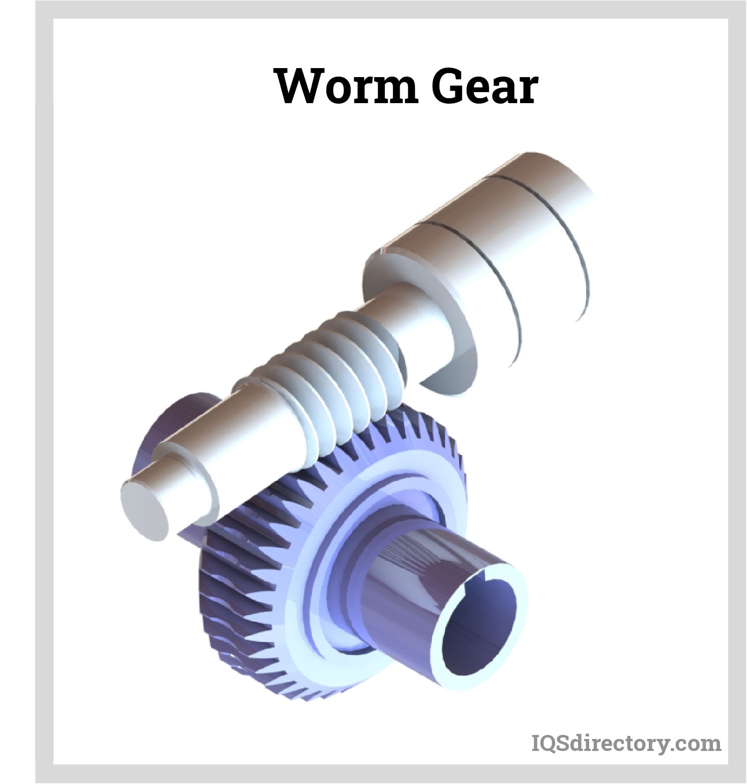
A central section of the mesh, taken through the worm's axis and perpendicular to the worm gear's axis, as shown in Figure 9-2, reveals a rack-type tooth of the worm, and a curved involute tooth form for the worm gear. However, the involute features are only true for the central section.

How to Calculate the Centre to CentreDistance between Worm and Wrom
The Worm Gear Torque Calculator is a tool used to calculate the torque or rotational force required to drive a system using a worm gear mechanism. It employs a formula that considers parameters such as the worm gear's lead angle, pitch diameter, and coefficient of friction to determine the torque required for efficient operation.

ZAR3 Worm Gear Calculation PDF Gear Windows Vista
Worm and WormGear Design Equations and Calculator Gears Engineering and Design Equations for American Standard Fine Pitch Worms and Wormgears Per. ANSI B6.9 P = Circular pitch of wormgear P = axial pitch of the worm P x, = in the central plane P x = Axial pitch of worm P n = Normal circular pitch of worm and wormgear = Px cos λ = P cos ψ
Worm Gear Design Calculation Pdf Converter highpowerdial
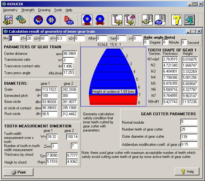
ZAR3+ generates true-scale drawing of worm and worm gear. ZAR3+ provides an additional input window for modifications of tooth height factors and profile shift coefficient x. These functions are useful for design of complementary gears of steel worm and plastic worm gear. ZAR3+ calculates tooth thickness and over pin/ball diameters (OPD).
Worm Gear What Is It? How Is it Made? Types Of, Uses
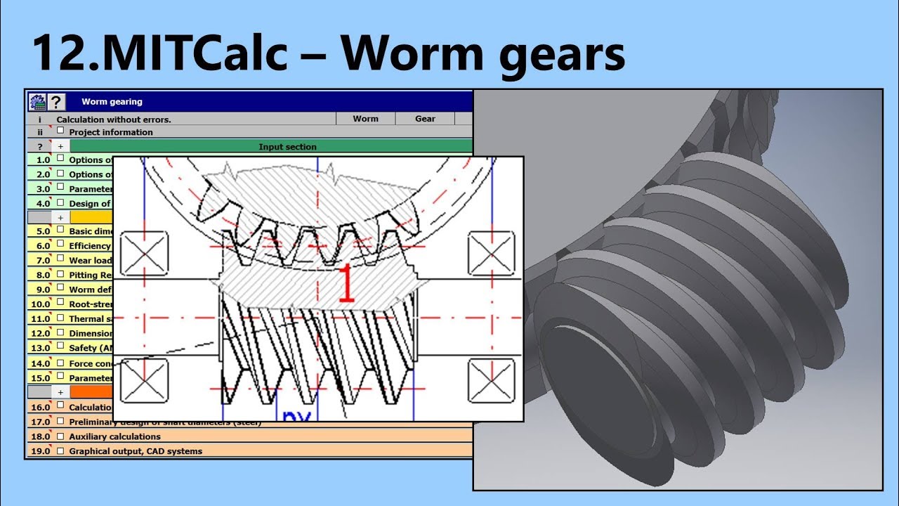
The calculation includes automatic design and solve dimensions, efficiency, losses, wear and pitting resistance, heating, safety, forces and more. MITcalc - Worm gear, geometric design and strength check.
Worm Gear Design Calculation Pdf To Jpg stseoseoxl
Worm gear sets are generally rated by their capacity to handle a particular level of input power, output power, or allowable torque at a particular speed for the input or output shaft. The AGMA power rating is based on pitting and wear resistance, as this is the usual failure mode for worm sets.
Worm Gear Design Calculation Pdf
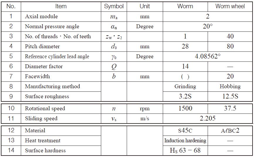
Gear ratio and tooth numbers . Pressure angle (the angle of tool profile) α. Module m (With ANSI - English units, enter tooth pitch p = π m) Unit addendum ha * Unit clearance c * Unit dedendum fillet r f * Face widths b 1, b 2. Unit worm gear correction x . Worm size can be specified using the: worm diameter factor q ; helix direction γ.
Worm Gear Calculation and Design (MITCalc12) YouTube
In this video we first hand draw a basic worm gear meshed with a worm wheel. Then we take a look at the function of a worm gear assembly and how to find the.
ZAR3 Worm Gear Calculation
The Worm Gear Ratio Calculator is a valuable tool designed to determine the gear ratio between a worm gear and a worm wheel (or gear) in mechanical systems. This ratio helps in understanding the rotational speed and torque transfer between these interlocking gears.
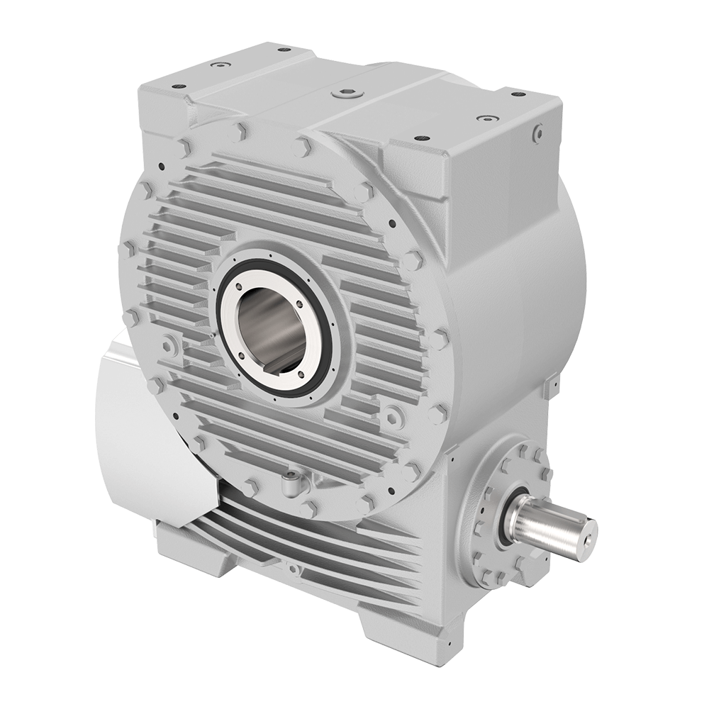
Competence in worm gear units for more than 120 years • AUMA Drives
This calculator will determine the axial thrust or load applied on a screw (worm gear) thread. Reference: Schaum's Outline Machine Design. Enter desired data within the boxes, calculations should be automatic. This calculator requires a java enabled browser. Open Screw Worm Gear Gear Axial Force Equation and Calculator

Worm Gear Calculation PDF Gear Force
Worm gearing is a special case of screw gearing with the angle of axes 90° and a low number of pinion/worm teeth (mostly z1=1-4). Worm gearing types are distinguished by shape as follows: Globoid worm/cylindrical wheel (not used) Types of cylindrical worms: .
How to Calculate Worm Gear Ratio? YD FORCE
The calculation is used for geometrical and strength designs and worm gearing check. The program solves the following tasks: Calculation of gearing dimensions. Automatic transmission design with minimum input requirements. Design for safety coefficients entered. Calculation of a table of proper solutions.
Download Worm Gear Calculator Program free software rutrackerxtra
(1) Standard Spur Gear Figure 4.1 shows the meshing of standard spur gears. The meshing of standard spur gears means the reference circlesof two gears contact and roll with each other. The calculation formulas are in Table 4.1. Fig. 4.1 The Meshing of Standard Spur Gears ( α=20°, z 1 =12, z 2 =24, x 1 =x 2 =0 )

DAV. Trocoide. Mechanical Design Apps Worm Gear Calculation
1 Scope. This document specifies formulae for calculating the load capacity of cylindrical worm gears and covers load ratings associated with wear, pitting, worm deflection, tooth breakage and temperature. Scuffing and other failure modes are not covered by this document. The load rating and design procedures are only valid for tooth surface.

Worm gear design calculation pdf sanycpa
Free Gear Calculator What is a gear calculator ? The gear calculator is a comprehensive software which, after inputting various parameters related to gear calculations, computes on-line automatically gear sizes, strengths, working forces, tooth forms, backlash conversions, etc.

Worm Gear Gears
This online calculator computes the raw toothed outlines of two meshing non-circular gears based on the polar equation of Gear 1 's pitch curve, the desired Gear 1 -to-Gear 2 pitch length ratio, desired number of teeth, and other parameters.
